
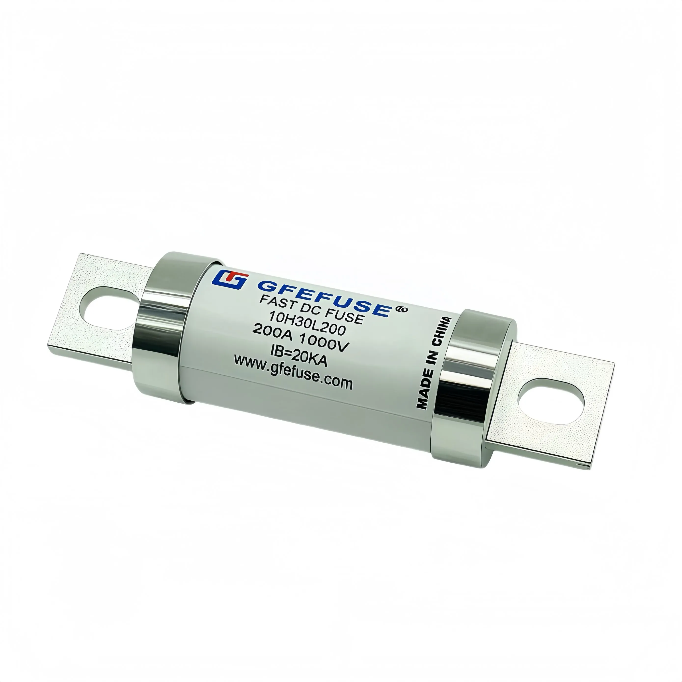
There are two ways to get vehicle high-voltage protection wrong. The first is a fuse that opens on a transient the contactor should have handled, leaving a driver stranded for a part that costs very little. The second is a contactor that tries to interrupt current beyond its capability, welds closed, and turns a manageable fault into a serious one. Both are coordination failures, and both are preventable on paper before a single part is fitted. This article explains how to divide the work between the contactor, the battery management system, and the EV fuse, using the two curves that decide it.
What Selective Coordination Means Here
Selective coordination means that for any given fault, the right device operates and the others do not. In a traction battery there are three layers:
- The BMS, which monitors cell voltages, temperatures, and insulation resistance, and can command a shutdown
- The contactor, which performs routine switching and is expected to clear moderate overcurrent under control
- The fuse, which is the final, autonomous device that acts when the other two cannot
The fuse has one decisive advantage: it needs no software, no control signal, and no power supply. That is why it is the last line rather than the first. It is also why it must not be asked to do the contactor's job.
Map the Operating Envelope First
Before comparing curves, write down what the system actually does:
- Maximum continuous current, including sustained climbing or towing conditions
- Peak current and its duration, for acceleration and regenerative braking
- Pre-charge inrush magnitude and duration
- The operating thresholds of the BMS protection functions
- The contactor's making and breaking capability, and its rated short-time withstand
- Prospective short-circuit current at the fuse location and the loop time constant
Most coordination failures trace back to a missing number in this list. In particular, contactor breaking capability is often assumed rather than read from the datasheet, and it is the number the whole coordination study rests on.
Draw the Two Curves on One Chart
Take the time-current band of the fuse and the operating characteristic of the contactor, and plot them on the same axes. You are looking for two things. First, in the overload region, the fuse curve must sit above and to the right of what the contactor is expected to handle. If the fuse operates first in this region, the vehicle shuts down on events that should have been managed by software and contactor, and you will see nuisance openings that are very hard to reproduce. Second, in the short-circuit region, the fuse must operate before the contactor is called on to interrupt current beyond its capability. The crossover point between the two curves is the practical boundary of the design, and it should be documented. Use the pessimistic edge of the fuse band for the second check and the optimistic edge for the first. That way the coordination holds across manufacturing tolerance.
The Overload Region Belongs to the Contactor
Overloads — sustained current above normal but far below a short circuit — are the BMS and contactor's responsibility. They are slow, measurable, and predictable, which is exactly the kind of fault a control system handles well. The fuse, meanwhile, should be thermally capable of sitting through the vehicle's entire duty cycle without cumulative damage. This is where derating and duty cycle analysis matter. A vehicle that repeatedly draws peak current for twenty seconds at a time puts far more thermal cycling through the element than one that cruises, and the selection has to account for the real profile rather than the average. If your fuse curve dips into the normal peak-current envelope, you have a problem that will show up as intermittent opening in the field, usually on a hot day during a hard drive.
Where the Fuse Must Take Over
Above the contactor's breaking capability, the fuse owns the fault. Three checks confirm it works:
- Breaking capacity exceeds the prospective fault current at the vehicle's maximum state of charge, with margin, at the rated voltage
- The rating is valid for DC at the actual loop time constant, not a generic AC figure
- Let-through I2t is below the withstand of everything in the fault path — busbars, connectors, cell terminals, and the contactor itself if it remains in circuit
That last point is easy to miss. Even when the contactor does not attempt to interrupt, it still carries the fault current until the fuse clears, so it must survive the let-through energy.
Pre-Charge Inrush and the Nuisance-Opening Trap
When a traction pack connects to a DC link with large capacitance, the inrush can be many times the nominal current for tens or hundreds of milliseconds. A pre-charge resistor limits it, but the residual surge still passes through the fuse. Two failure modes follow. If the pre-charge circuit is undersized or the resistor bypassed by a control error, the fuse absorbs an inrush event it was never sized for. If the same happens repeatedly, cumulative thermal damage reduces capability long before any visible symptom appears. The fix is to check the inrush against the fuse's pre-arcing I2t, count the events over the vehicle's service life, and confirm the cumulative duty is within what the device can absorb. This is a ten-minute check that prevents a whole class of field returns.
A Coordination Checklist
Before sign-off, confirm each of these in writing:
- Maximum continuous and peak duty cycle current established and derated for enclosure temperature
- Fuse time-current band plotted against contactor capability
- Crossover point identified and documented
- Pre-charge inrush I2t calculated and compared against pre-arcing capability
- Breaking capacity confirmed at maximum state of charge and actual time constant
- Let-through I2t below the weakest component in the fault path
- Voltage rating at or above maximum pack voltage including regenerative overshoot
Summary
Coordination is not a single calculation but a division of labour. The BMS and contactor handle what is slow and measurable; the EV fuse handles what is fast and destructive. Plot the curves together, check both the overload and the short-circuit region, and account for pre-charge inrush, and the design will neither nuisance-trip nor weld a contactor.
About Our Vehicle Protection Range
GFEFUSE is the brand of Dongguan Gongfu Electronics Co., Ltd., an electronic protection device manufacturer founded in Dongguan, Guangdong in 2013. Our integrated development, production, and sales team is supported by five advanced production lines and thirteen R&D engineers, and our products are exported to customers overseas. Our EV fuse range covers high-voltage DC protection for traction batteries and charging systems, and it is frequently specified together with our bolt down fuse options where a bolted busbar connection is preferred over clip mounting. The wider high voltage fuse portfolio supports the rest of the vehicle DC chain, and for stationary applications our energy storage fuse range covers battery cabinets and containers. Products carry UL, cULus, TUV, CE, and CQC certification and comply with RoHS and REACH directives, serving automotive electronics, new energy, power equipment, communication systems, and consumer electronics.
Conclusion
A well-coordinated design is invisible: nothing opens that should not, and everything opens that must. Getting there requires two curves on one chart, an honest contactor datasheet, and an inrush calculation. Do those three things and the protection will behave predictably across the vehicle's whole service life.
Send us your pack voltage, continuous and peak current, pre-charge inrush profile, and contactor breaking capability. We will plot the coordination and recommend a rating and mounting style.
Frequently Asked Questions
Short answers on coordinating vehicle high-voltage protection.
How do I coordinate an EV fuse with the battery contactor?
Plot the fuse time-current band and the contactor operating characteristic on the same axes. In the overload region the fuse must sit above what the contactor clears. In the short-circuit region the fuse must operate before the contactor is asked to interrupt beyond its capability.
Why does my EV fuse open during pre-charge?
Because the inrush energy exceeded the pre-arcing capability, often due to an undersized pre-charge resistor or a control sequence error. Compare the inrush I2t with the datasheet value and check the resistor and timing.
What breaking capacity does an EV fuse need?
It must exceed the prospective fault current at maximum state of charge, at the pack voltage, and at the actual loop time constant of the vehicle harness. Confirm the DC rating rather than relying on an AC figure.
Should the fuse or the contactor handle overloads?
The contactor and BMS, in most designs. The fuse is the last line and should tolerate the full duty cycle without cumulative damage. If the fuse curve dips into the normal peak current envelope, expect nuisance openings.
Does the contactor need to survive the let-through energy?
Yes. Even when it does not attempt to interrupt, it carries the fault current until the fuse clears, so its withstand must exceed the let-through I2t of the protective device. This separation is what makes the EV fuse layer both a redundant check and a faster one than the contactor can ever be, and it is the reason every modern traction system carries one.